Component assembly
What you’ll find here and what not…
This assembly guide is not the “a) connect this to that b) now screw together blabla” type of guide, but more an overview of how things go together in general. I.e. I will not give an exact type, length or amount of screws, nuts and bolts for most of the parts, especially because sizes are not that critical in most cases or because, for some people, metric hardware won’t be easily available in some countries.
But as a rule of thumb
- use washers wherever appropriate (don’t force the screw heads into the plastic)
- screws for the basic frame are M5
- the carriage mover needs M3-M6
- the belt tensioner depends on M4
- most of the other and smaller parts, like endstop mounts, yarn sensor, control box, etc. need M3.
Many of you will already have a decent assortment of screws, nuts and washers in different sizes at home, so it is up to you. If you really run into problems and don’t know what to do, feel free to contact me via Printables.
Depart from that, in case it is necessary to maintain functionality I will be more precise.
If your T-nuts can only be slid in from the sides of the extrusion, make sure that you have enough T-nuts in place before beginning to screw things down. Don’t ask me how I know, that you would have to disassemble more or less parts again, if a T-nut is missing…
I will describe the main components a bit more in depth now, but you will have to take a decent look at the photos and CAD drawings to get the whole picture of how it is done. As I said, the built is not for the faint-hearted :D
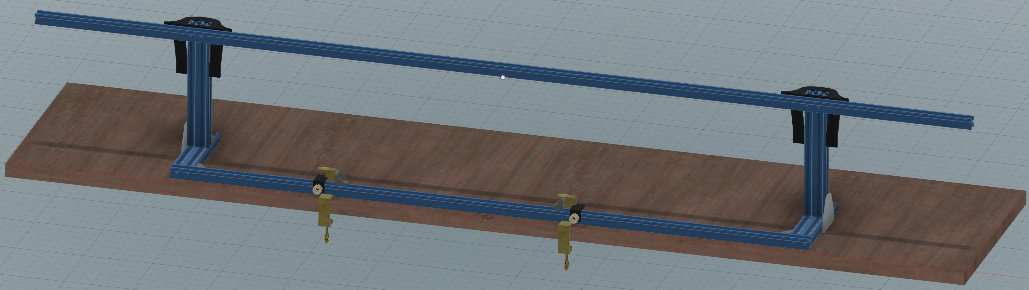
1) Frame
| Frame only |
|---|
 (click to zoom) |
I left out the knitting machine in this picture for better visual clarity. In reality, because of the table clamps, you start by fixing the knitting machine to the table, because you simply place the frame around it.
Assembling the frame first and bolting everything to the table later is totally possible though. I screwed the whole frame together, fixed the machine to the table and positioned the frame. Here is how…
Wording, or how I call the extrusions to name them independently:
- top horizontal long extrusion: run bar
- bottom horizontal long extrusion: front rest bar
- right/left horizontal short extrusions: feet
- right/left upright short extrusions: posts
The frame itself
- The frame is straightforward. Use the corner brackets to connect the front rest, feet and mount post extrusions and make sure everything is square. I only used the corner brackets, but for added stability you could drill holes in the front rest bar, cut threads into the feet and screw them together. But it really isn’t necessary. Regarding position of the posts, you can start about 105mm from the front rest bar as a starting point. You will have to fine adjust their horizontal (back to front) position later, when the carriage mover is attached.
- Add the
frame T-joining plate.stls at the sides for stability and stiffness. - Loosely screw the
frame barclamp.stls in combination with theframe vertical stiffner left.stlandframe vertical stiffner right.stl(naming is according to looking at them from behind the machine) to the run bar, then slide the clamps over the posts on both sides, leaving about 5mm of each post free above the clamps. Lock the barclamps and stiffners down, make sure, the run bar is positioned equally distant over the knitting machine. The height is a starting point. You may have to adjust the height of the run bar later when attaching the carriage mover though.
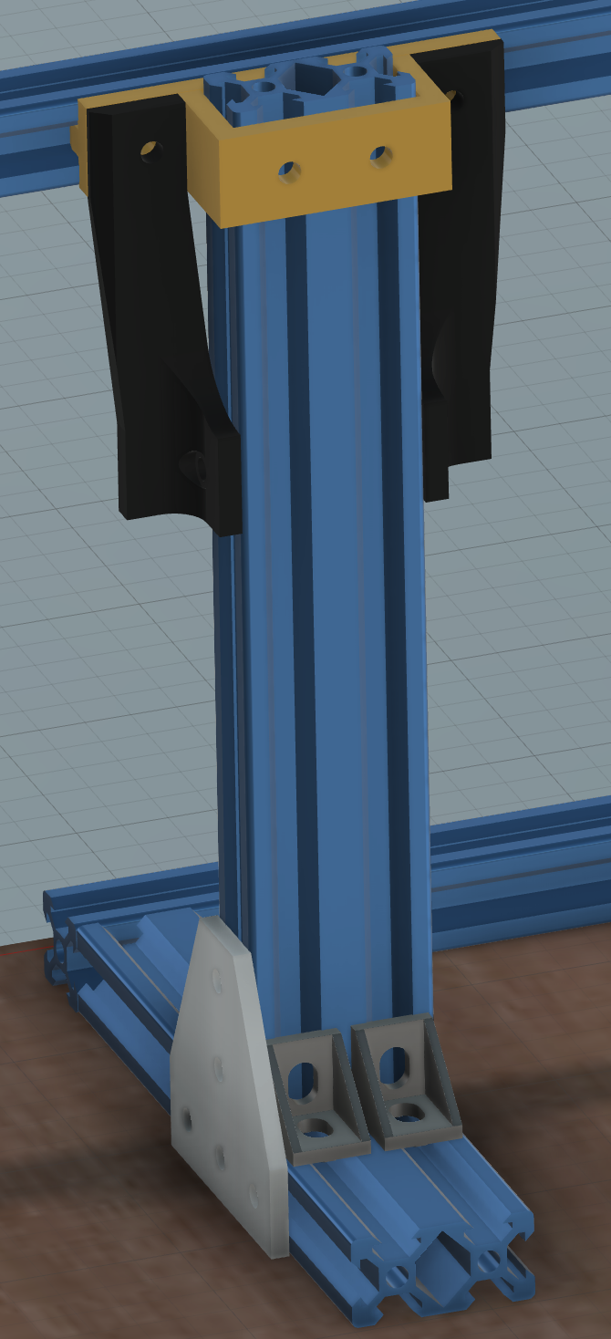
| Post back |
|---|
 (click to zoom) |
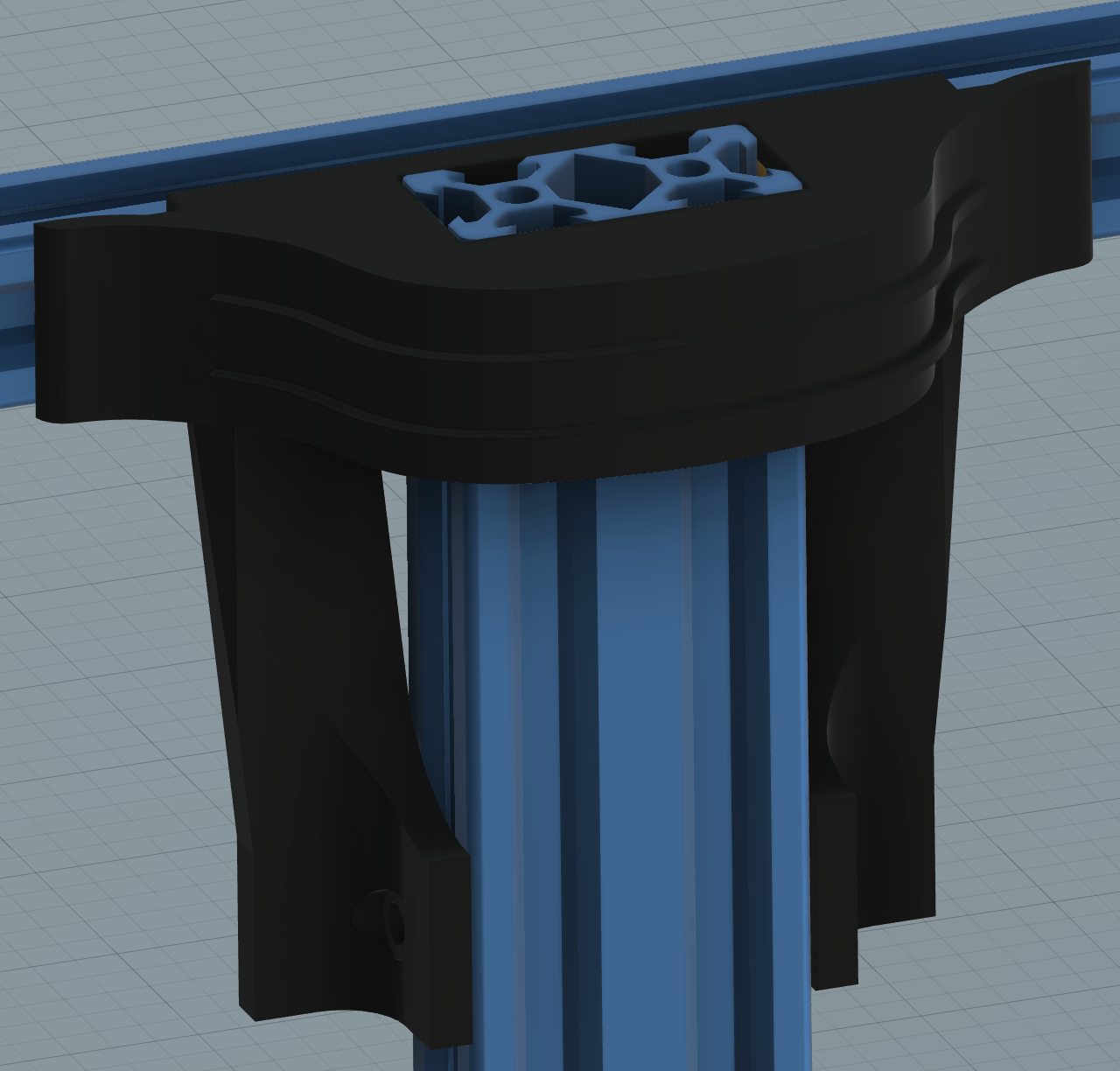
- Slide the two
frame belt slider.stlover the top of the posts and see if everything fits together nicely. The two sliders are for general protection and to hide the cables for the endstops later.
| Post back with slider |
|---|
 (click to zoom) |
- Add the last two corner brackets to the top groove of the rest bar and slide them both to the middle of the bar. Their upright edges have to point away from each other.
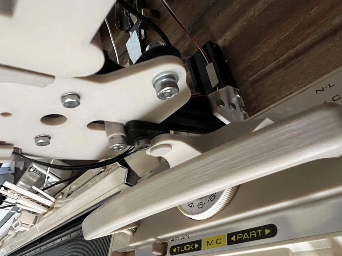
Mounting everything to the table
-
Use the ribber clamps to fix the knitting machine to the table.
-
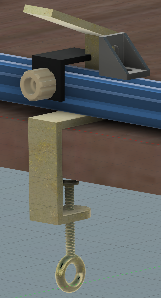
Now position the frame over the machine, so that the rest bar sits on the inward curve of the machine clamp (see picture) and that the machine is evenly spaced between the feet of the frame. And before you ask, yes, that will tilt the whole assembly a slight amount to the back and that’s totally fine :-)
-
Slide the two corner brackets in the top groove of the rest bar outwards until they hit the ribber clamps, screw them down.
-
Slide
frame main clamp left.stlandframe main clamp right.stlinto place and screw them down with an M5 bolt, for convenience supported via aM5_screw_knob.stl. These nice knobs will will make removing the whole frame when disassembling much easier.
| Front rest with clamp |
|---|
 (click to zoom) |
Positioning of the left and right endstop switches
At first mount the endstop switches to the endstop_mount.stl and then loosely fit them to the left and right end of the run bar. Later, after you have attached the carriage mover, you will have to adjust their position so that the carriage can be moved over the whole bed from left to right or even a bit further, i.e. to use a color changer.
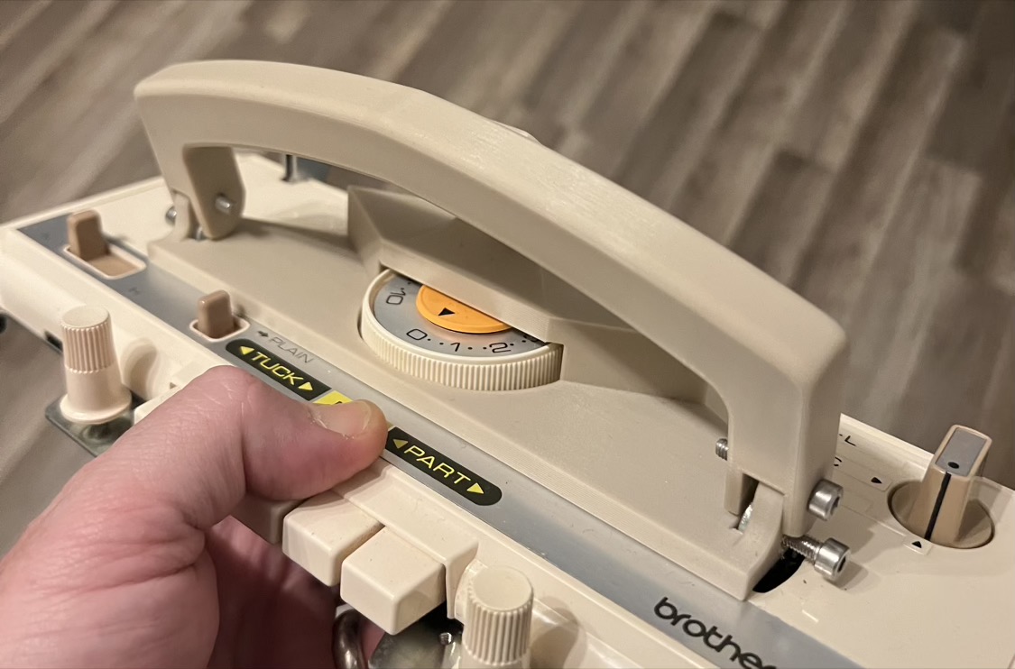
2) Carriage adapter
No CAD images here. Remove the original handle from the carriage by removing the two grub screws. Then slide the carriage adapter plate in position and screw it down. Last, attach the new handle bar.
(click to zoom)
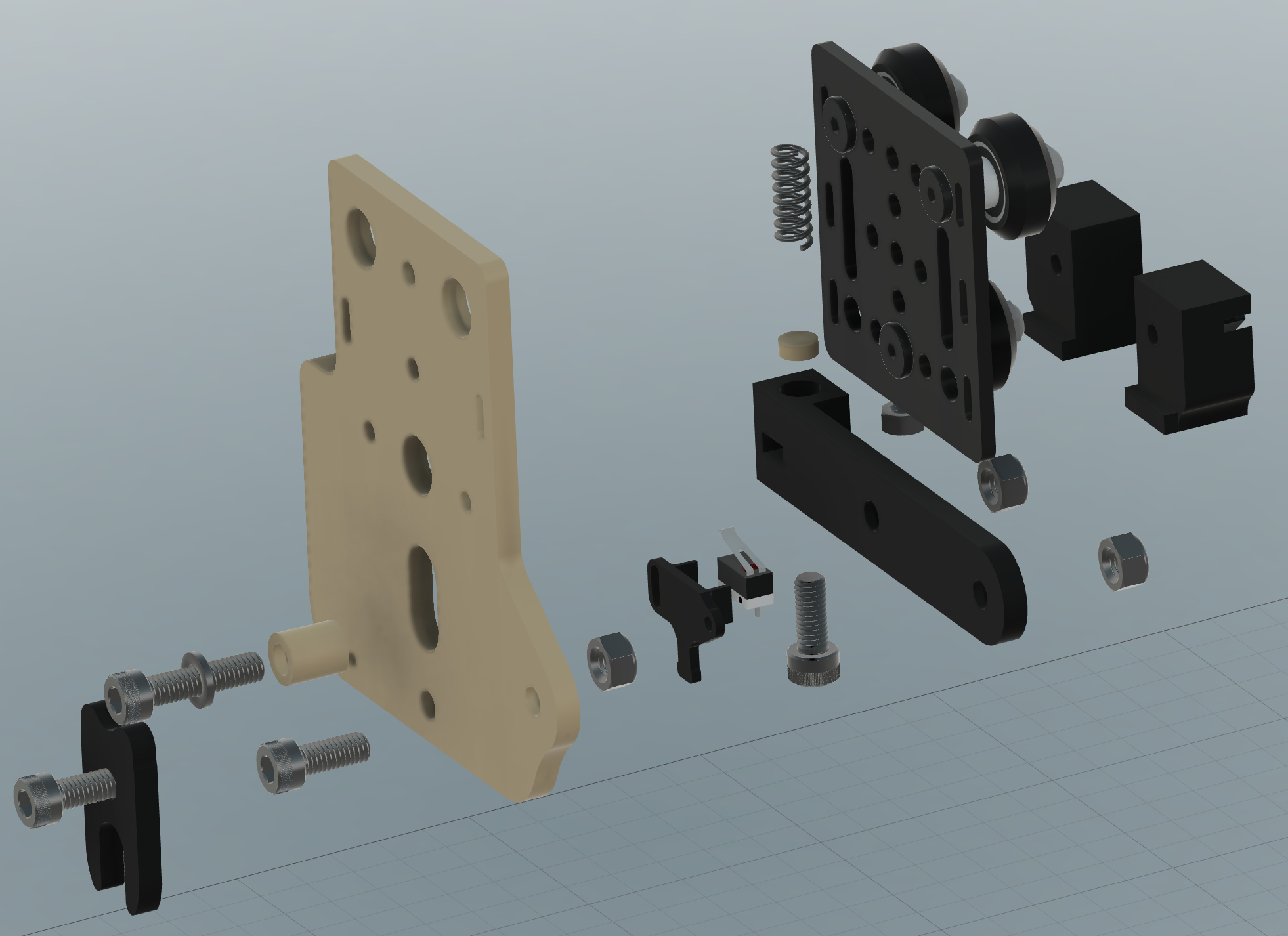
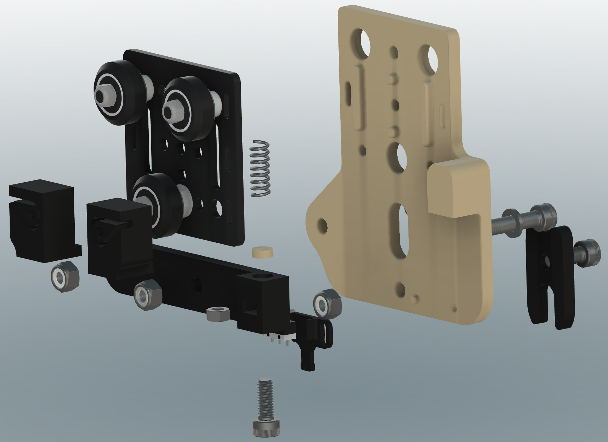
3) Carriage mover
| Mover front | Mover back |
|---|---|
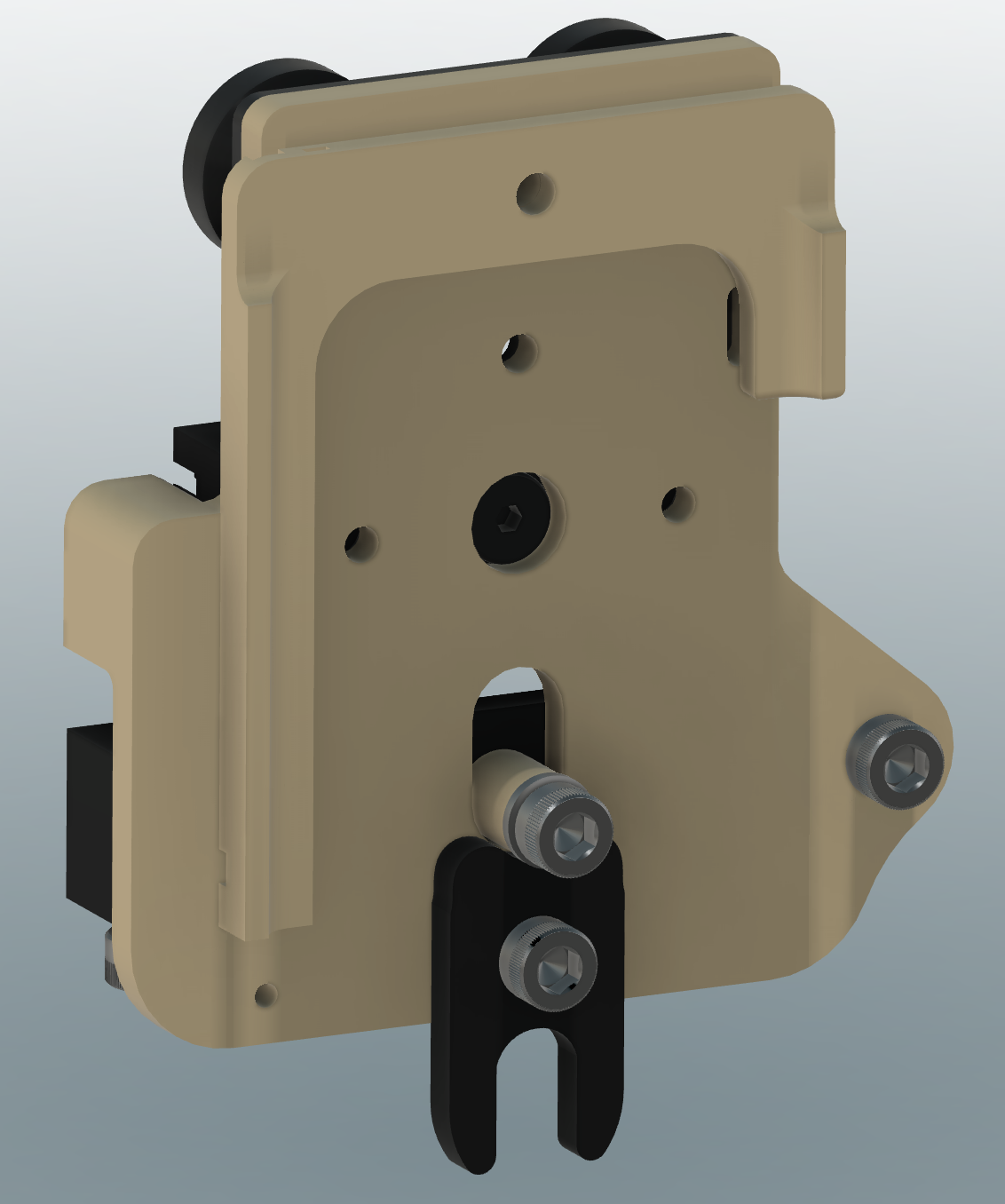 (click to zoom) |
 (click to zoom) |
See the following pictures on how to assemble the carriage mover.
- The screws I left intentionally in the picture have to be M6.
- The gantry is fixed by using M4 screws.
- For the
mover belt holders left/right.stluse M3 screws and support them with washers. - The
mover overload sensor mount.stldoes need an addtional M3 screw, this one can be screwed in to the plastic carefully.
If you bought a 4-wheel 2020 gantry, simply reassemble it to a 3-wheel version.
BEWARE: I MISSED the endstop bracket.stl in the exploded views, but I think you get the point from the front and back images above.
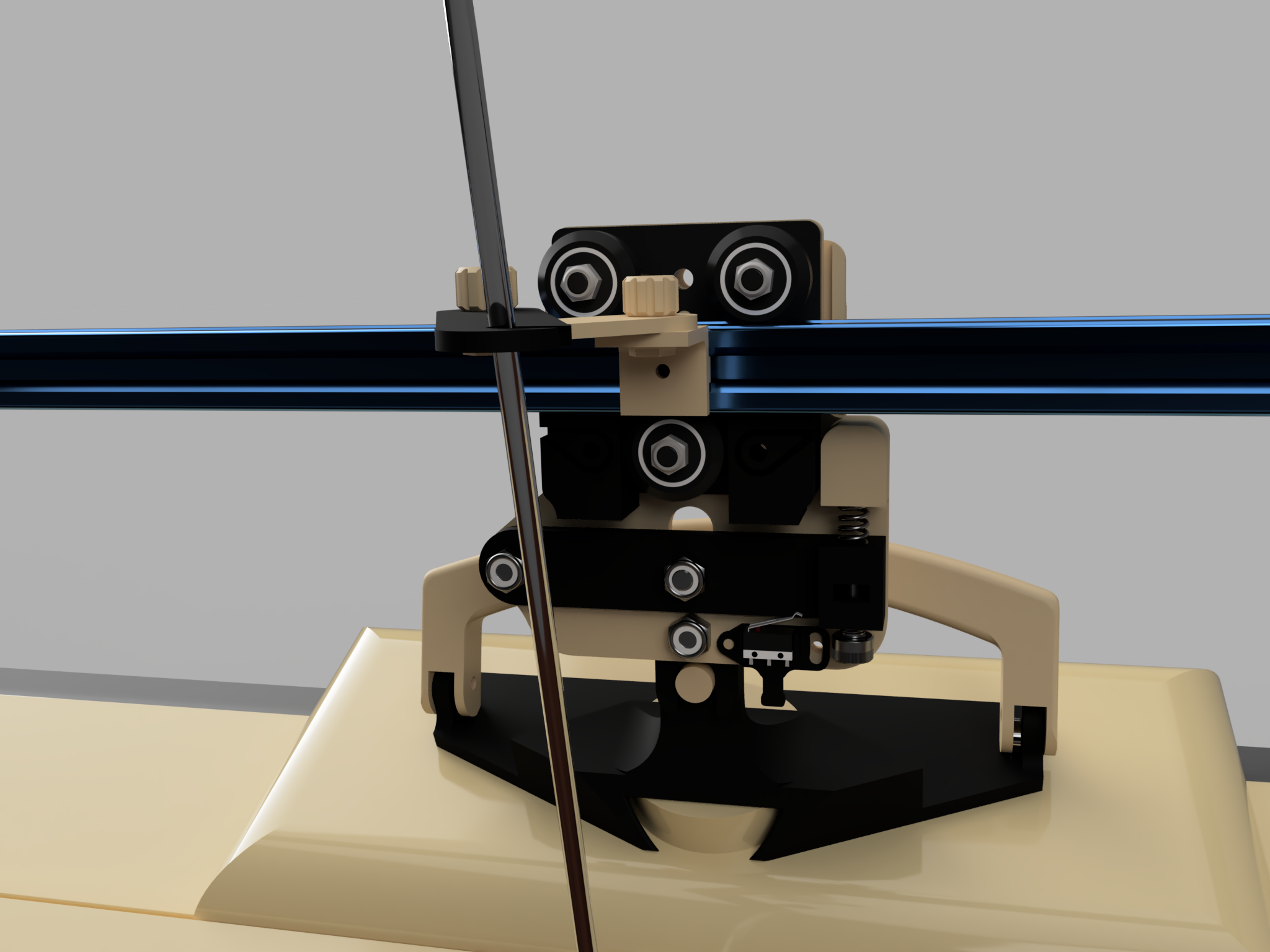
| Mover assembly front |
|---|
 (click to zoom) |
- You don’t have to attach the
mover overload sensor mount.stland the little switch right now. You can add it later while assembling the electronics. The switch cable though has to be guided on the left side around themover plate.stlto the front, can then be guided through the small channel on the backside ofmover endstop bracket.stland fed to the top of the plate.
| Mover assembly back |
|---|
 (click to zoom) |
- The small
mover spring presser.stl, which helps compressing the spring with the tensioner screw, is shown only once on the pictures. If you find that your compression spring is not strong enough, before grabbing a new one, add a secondmover spring presser.stlon the top of the spring. This might help already.
If everything went together well, try to slide the mover over the run bar to see if it runs smoothely and without any wobble or wiggle. If it is too tight or too loose, you have to adjust the position of the rolers. If you don’t know how, OpenBuilds setup video on YT, beginning 2:38 is your friend, but as a hint, two of the rolers are mounted excentrically and you can adjust their position.
Frame adjustment
Now, with the carriage mover attached to the run bar you can fine tune the whole frame.
- slide the carriage to the middle of the bed
- slide the carriage mover to the middle of the bed, straight above the carriage
- add the
carriage bolt.stto the carriage adapter and see if it couples the carriage to the mover - adjust the position of the posts back to front and the height of the run bar, so that the coupling mechanism connects easily and without much play
- slide both to the far left and far right to see if there are any positional inconsistencies you might have to fix
Take this as reference:
(click to zoom)
Overload spring adjustment
The tension of the spring has to be adjusted in combination with the belt tension. The most accurate way is by knitting a test piece with the tightest stich possible. Start with the lowest spring tension possible. The spring lever should not wiggle around freely up and down, but should be pressed firmly against the spring. If you find that the mover disconnects from the carriage too easily while knitting your test piece, increase the tension of the spring. It should be tight enough so that you are able to knit everything you want, but not so tight that the mover won’t disconnect in case of a blockage of the carriage, which on the other hand can lead to the timing belt slipping or even damaging your carriage. So be careful when dialing in the correct tension.
Overload sensor position adjustment
You will have noticed, that you can adjust the position of the overload sensor closer to the spring lever or more far away from it. This helps to get the moment where it triggers just right. Its main function is to stop the mover when there is a blockage of the carriage and the coupler has disconnected. As this depends on spring tension and how you setup the strength of the spring lever action, I can only give a general advice here. You have to setup the sensor trigger point in a way that it will be activated in the moment the spring lever is raised up and has disconnected the mechanical coupling to the carriage.
Regarding mover_plate_v2.stl
| Mover plate v2 |
|---|
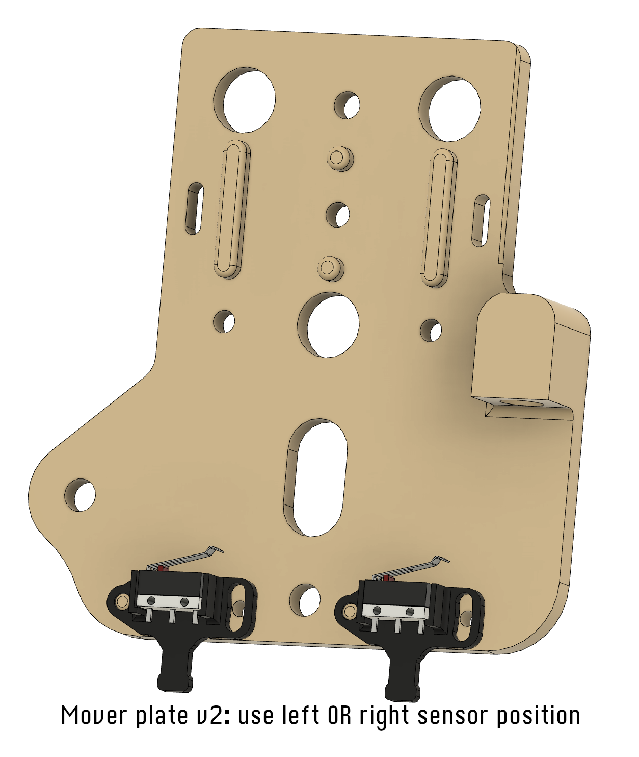 (click to zoom) |
I noticed that fine adjusting the overload spring and overload sensor position can be a bit tricky, if the switch is in the front position (near to the spring), because the spring lever is moving in a wider range up and down at its front than at its back. So I added a second (optional) sensor position more to the back of the lever, where a more finer adjustment of the sensor position will be possible. Choose whatever position is suitable for the spring and switch combination you bought.
Keep in mind, in case of a blockage the goal is to first) have the carriage mechanically disconnect from the mover before second) the switch opens - at least shortly one after the other.
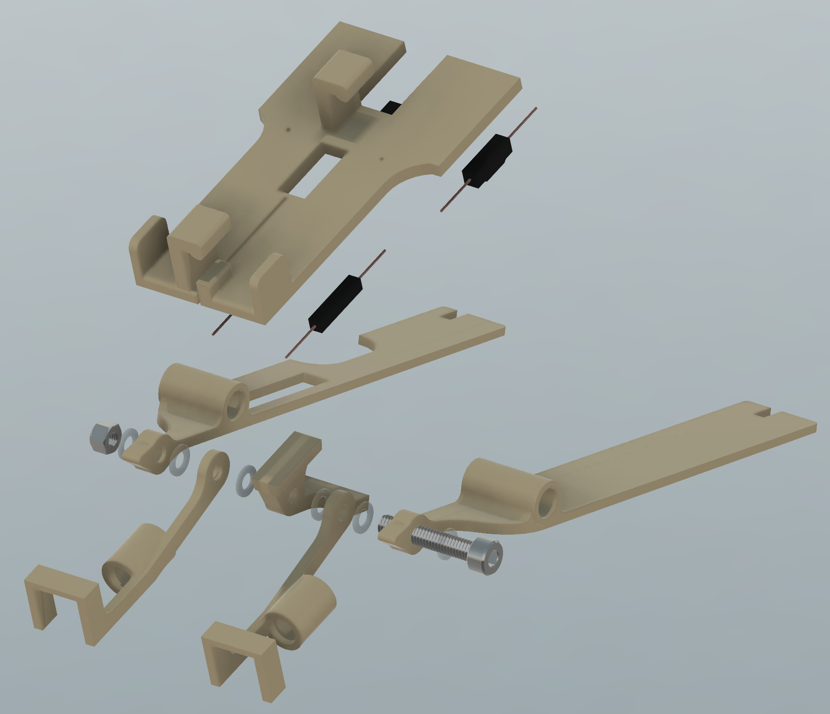
4) Yarn sensor
| Yarn sensor assembly |
|---|
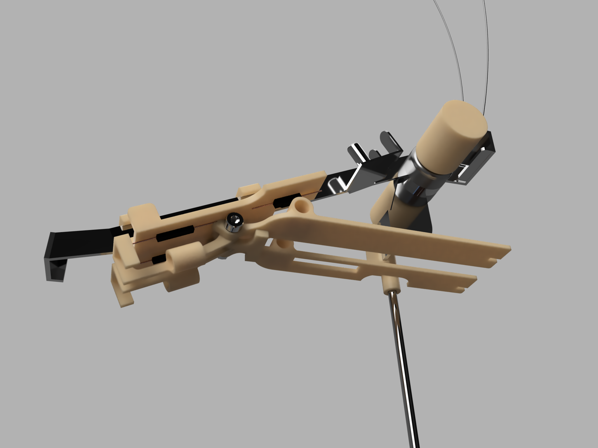 (click to zoom) |
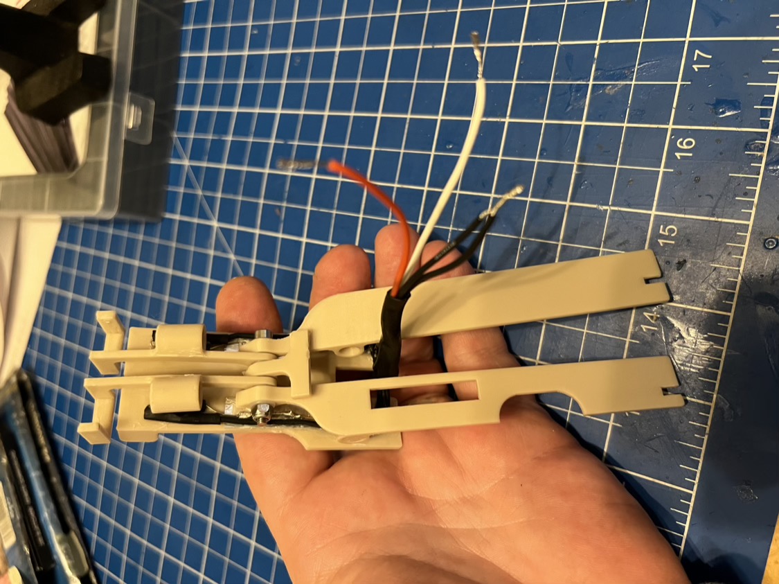
The yarn sensor is the most complex and intricate build of the whole system. As it would be a bit hard to describe how everything goes together, I suggest taking a closer look at the photos to see how it is done.
How does it work?
The yarn sensor is capable of sensing a) yarn runout and b) knots in the yarn for the main (right) and the secondary (left) thread. To achieve this, there are four reed (aka magnetic) contacts on the underside of the sensor which act in combination with the four levers, which are equipped with a small magnet each. Every lever / reed contact combination will therefor form a single switch and the two sensors (front and back) on each of the sides will form a unit, which means both sides are measured independently, but always the front and the back sensor element together. So, if either the right runout sensor lever (front) or the right knot sensor lever (back) is engaged, the control box will report an error regarding the right (main) yarn sensor - same for the left (secondary) side.
Yarn runout
The switch in the front will be closed when yarn is fed through the sensor, as the thread will hold the corresponding lever up, which will close the reed contact. If the yarn runs out, the lever will drop, which will open the contact and can then be sensed by the control box.
-> The contacts in the front are “normally open” reed contacts.
Knot sensing
If a not comes up from the cone it will be trapped in the small slit in the back lever, raise the lever and, in this case, open the reed contact. This will also lead to a message on the display of the control box.
-> The contacts in the back are “normally closed” reed contacts.
| Yarn sensor top | Yarn sensor bottom |
|---|---|
 (click to zoom) |
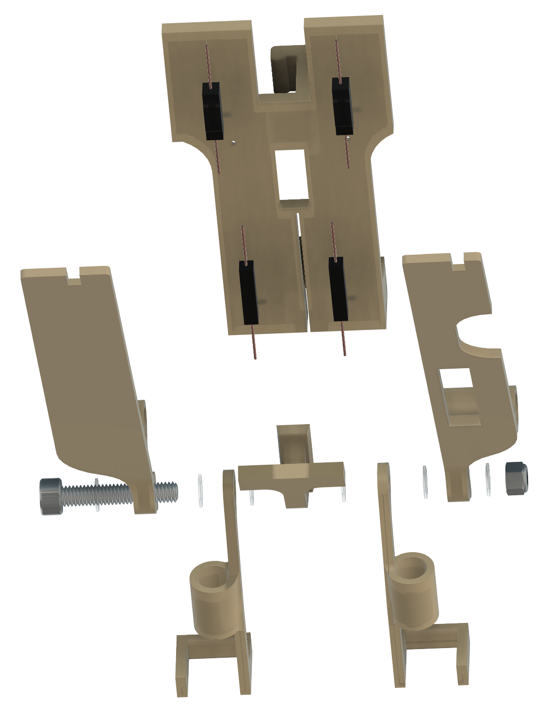 (click to zoom) |
I recommend taking a look at the pictures I took during the build so that you can see how the reed contacts have been placed and how the wiring is done.
Assembly
- The main plate consists of two parts,
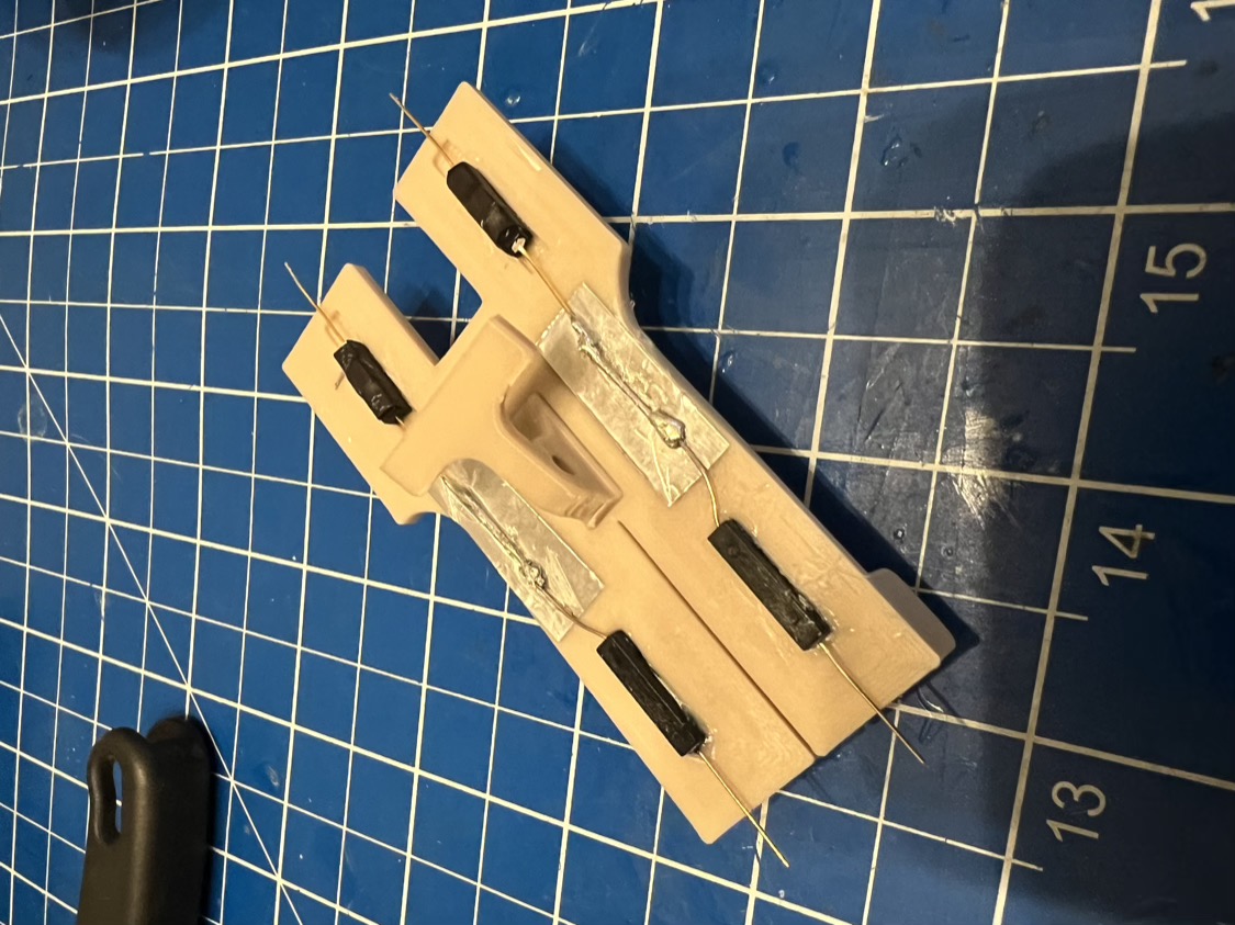
yarn sensor base.stlandyarn sensor base screw mount.stlto make it easier to print. You have to insert theyarn sensor base screw mount.stlfrom the top of the base plate (mind its orientation, the fin has to point to the rear of the plate!) and glue it in place. Make sure it is sitting flush and straight in its position. - Glue the reed contacts into place (small recesses). That means, the two “normally open” contacts in the front and the two “normally closed” ones two the back. Double check that you are about to glue the right ones into place! I recommend to temporary fix them to the plate and check with a multimeter and a magnet if their orientation is just fine and if they react to the distance of the magnetic as necessary. Especially the “normally closed” ones in the back should be checked. They have a small hump on one of the four sides and this hump should be facing downwards. The “normally open” reed switches don’t have this hump and are not as sensitive to misorientation than the others.
- Then, on either side, connect the front contact two the back contact. If you take a look at the photo I took during the build you can see, that I put a little piece of adhesive aluminium tape under the connection and soldered both contacts as flat as possible together. If you want to do it the same way, keep in mind, that you solder above plastic. Try to position the solder point the same way as I did, because you need some room inward between the solder point and the screw mount. The back lever (knot sensor part) which we attach later has to be able to move freely up and down and should not be blocked by the solder point.
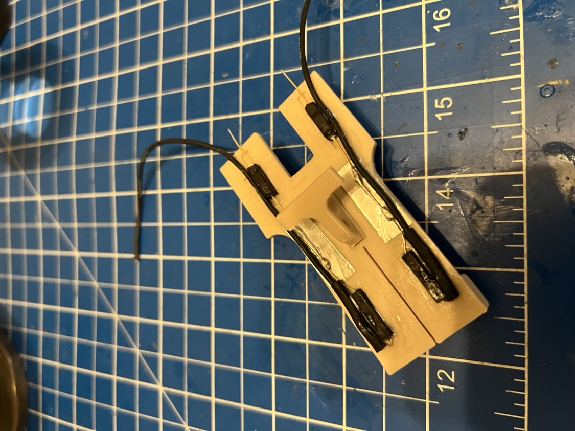
- Next, begin to attach the cables to the contacts. See this photo how I did that. Guide the front cables to the back, then attach the back cables. You should secure the cables by glueing them right to the base plate, so that they will not interfere with the levers. You can use CA glue as me, or a thin (!) layer of hot glue. There is not much room for everything, but I think you get the point. I used a little bit of shrink tubing to make sure nothing comes in contact with each other. You can now connect the two cables coming from the front of either side together, but leave the two cables from the back separated, so that you now have 3 connections which will later be attached to the stereo jack: the two single cables to tip (main) and ring (secondary), and the two connected ones to the sleeve contact.
- After that, it is just a matter of a bit of smart cable management - I used a little bit of a somewhat stiffer shrink tubing to model the way the cables go between the back lever arms. As soon as the shrink tubing cooles down, the cables will be fixed and won’t interfere with anything anymore. You can also see there what I meant by 3 cable contacts that I mentioned earlier.
- Now, assemble the levers. I used nylon washers between everything to have as little friction as possible. You can also use thin metal washers, but you cannot omit them completely, as the tolerances between all parts account for them.
- Add the magnets to the little tubes, but don’t glue them into place right now, we have to fine tune their position first.
Adjust the mechanical play
Use a nylon lock nut along with the central screw to adjust the play of the lever movement. The four levers should move up and down freely, but make sure that they don’t wiggle around sideways, as this will lead to unreliable behaviour, especally with the back (knot) sensor elements. Using a lock nut is a good way to adjust the play in very small steps, as the difference between too loose and too tight is rather small.
Fine tuning of the magnet positions
The magnets have to be placed inside the small tubes of the front and back levers in a way that moving the levers up and down will activate or deactivate the corresponding reed contact directly above them. I can only give a general advice for calibrating the magnet position, because I don’t know the actual strength of the magnets you bought, but you have to position the magnets in such a way, that
- the front levers can actually move a little bit up and down without deactivating the reed contact, but open the contact when you let them swing down completely
- the back levers (which have much less room to move up and down!) should open the reed contact only when the lever is really close or touching the reed contact
If the force of the magnets is too strong, it can help to move them sideways in relation to the reed contact inside the tube to reduce the magnetic field impact. Use a multimeter connected to the back and front reed contact to see if it works.
The multimeter should detect a closed connection when
- a) the front lever is in up and
- b) the corresponding back lever in its down position.
If you are happy with how everything works, simply glue the magnets in place so that they cannot leave their calibrated position anymore. To even more secure the magnets you can insert one of the small yarn sensor magnet plug.stl on either side of the tube and glue them into place, too.
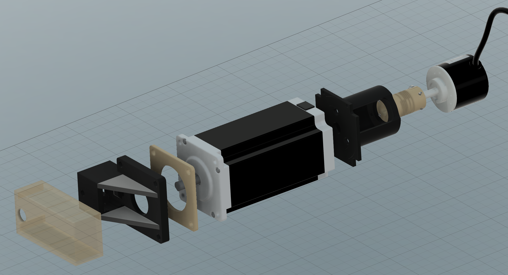
5) Stepper and rotary encoder assembly
| Stepper assembly | Rotary encoder assembly |
|---|---|
 (click to zoom) |
 (click to zoom) |
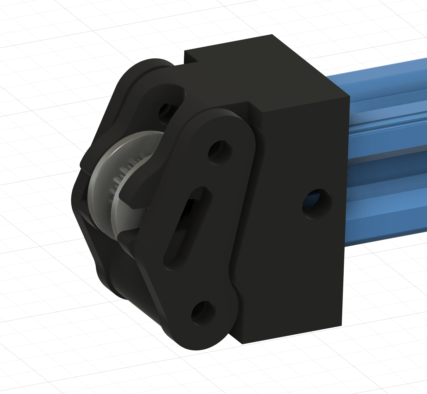
Assembling the attachement for the rotary encoder and completing the whole stepper motor setup is really straight forward. Although the rotary encoder shaft coupler.stl between the rear motor shaft and the rotary encoder will allow for some misalignment, try to make sure that there is no play in the back assembly and that everything is tight and straight.
As a last step, slide the frame stepper mount.stlover the right end of the run bar. The stepper assembly has to point to the back. At first, just barely screw it down. After having attached the timing belt you can then first pull the stepper assembly outward and screw it down to pre-tension the belt before further tensioning of the belt with the belt tensioner on the left.
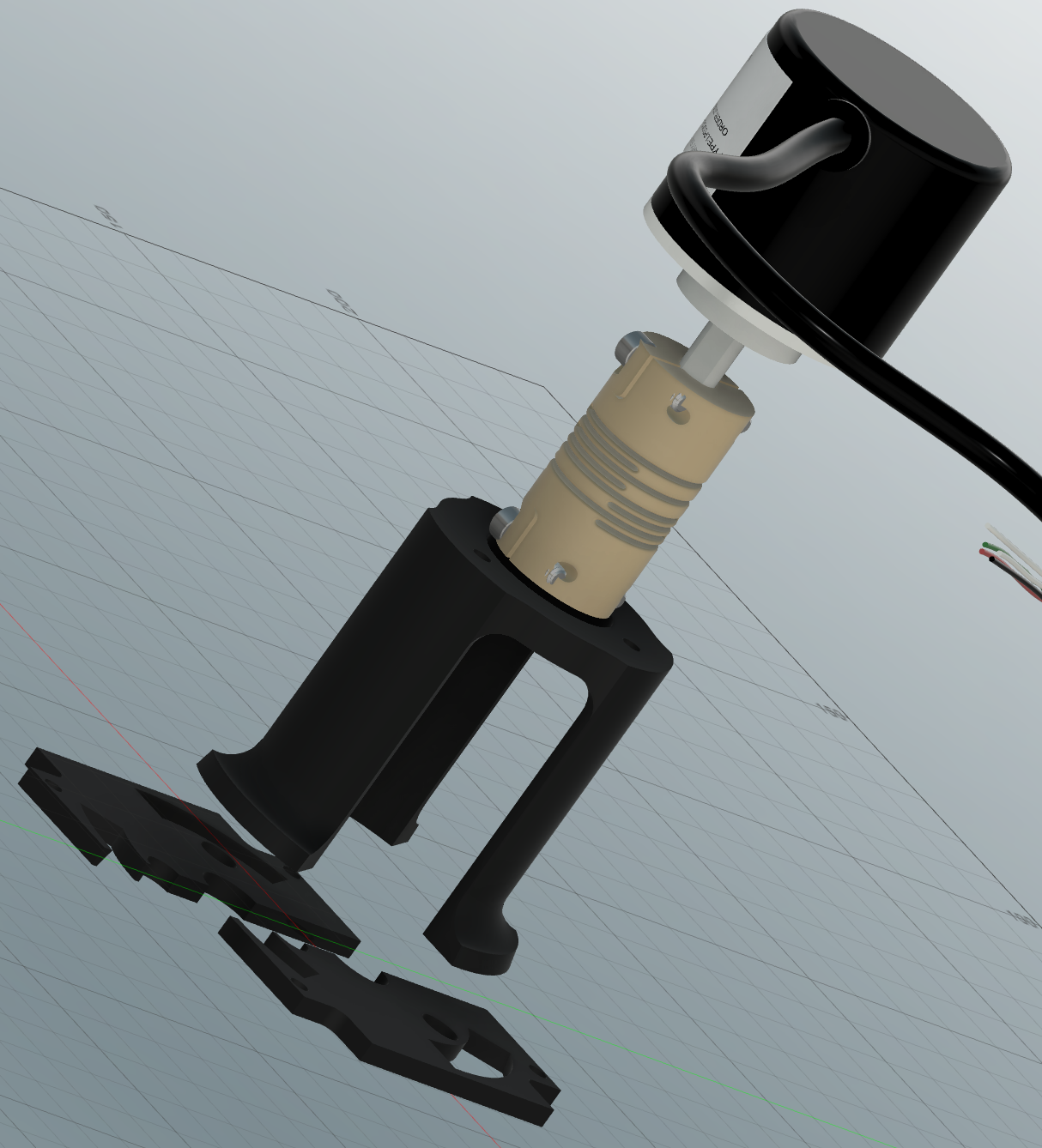
Regarding the rotary encoder bracket
The bracket consists of three parts for easier and support-less printing:
rotary encoder bracket base left.stlrotary encoder bracket base right.stlrotary encoder bracket bridge.stl
It can be a bit fiddly to get all three parts together and you will have to bend the legs of the bridge a bit until everything snaps together. As a hint, you should first insert the legs of the bridge into the base parts from the top and then lightly force everything into place. I assure you it will work, work slowly and carefully.
6) Belt tensioner
| Belt tensioner |
|---|
 (click to zoom) |
Use M4 screws, washers and nuts to assemble everything. Take a close look at the picture to find out the correct direction of the arms left and right. The tensioner screw has to go on the underside of the run bar. If you screw the tensioner screw inwards, it pushes against the belt_tensioner_pusher.stl and will then move the idler pulley outward. This will tension the belt.
I know that the bore hole of the GT2 idler pulley is 5mm, but we are using M4 screws here. This hasn’t led to any problems in my setup. If you are worried about that, simply widen the slot where the screw is sliding up and down in the arms and use a M5 screw instead.
Attaching and tensioning the belt
-
Unscrew the tensioner screw the whole way out
-
Attach the belt to one side of the carriage mover by sliding a small loop into the belt holder - the belt will be secured by friction and grabbing itself, use the
GT2_clip.stlto secure it -
Now guide the belt around the frame - it has to run through the upper and lower groove of the aluminium extrusion - thread it through the tensioner and the stepper mount
-
Take out the slack as good as possible and attach the loose end to the other side of the carriage mover, use the
GT2_clip.stlto secure it -
Now tighten the tensioner screw again to further tighten the belt, but please don’t overtighten it!
As a guideline:
The belt tension and the tension of the overload spring on the carriage mover depend on each other. The whole adjustment should be set up in a way that, under normal conditions, the belt doesn’t slip while knitting and it shouldn’t slip also when the carriage is blocked, so that the coupler mechanism can disconnect the carriage from the mover. But if your overload spring is too tight, then the belt might slip anyhow and the carriage will never be disconnected.
-
If the belt feels quite tight, knit a test piece with the tightest stich setting. If the carriage mover starts to slip while knitting normally, re-tighten the belt.
- Try to block the carriage during its movement with your hands - do that without having any needles engaged, just for safety. If the belt slips before the carriage coupler disconnects the carriage, re-tighten the belt.
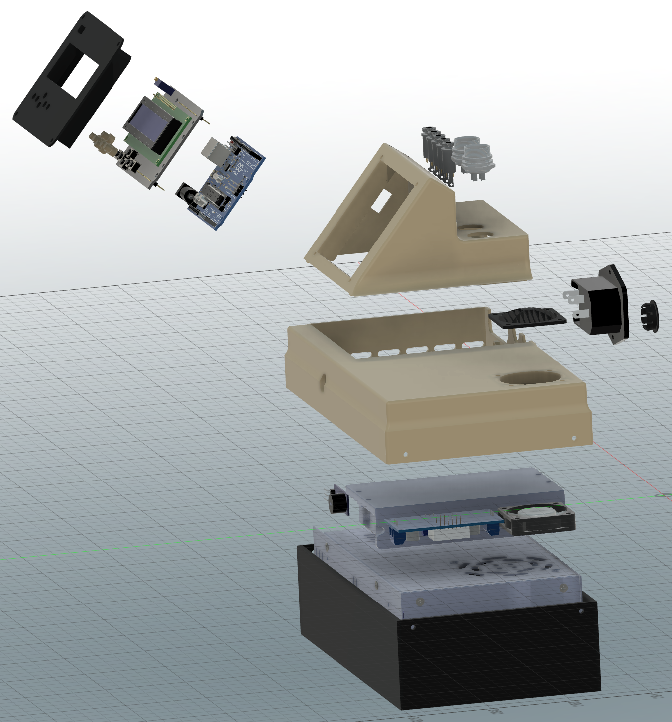
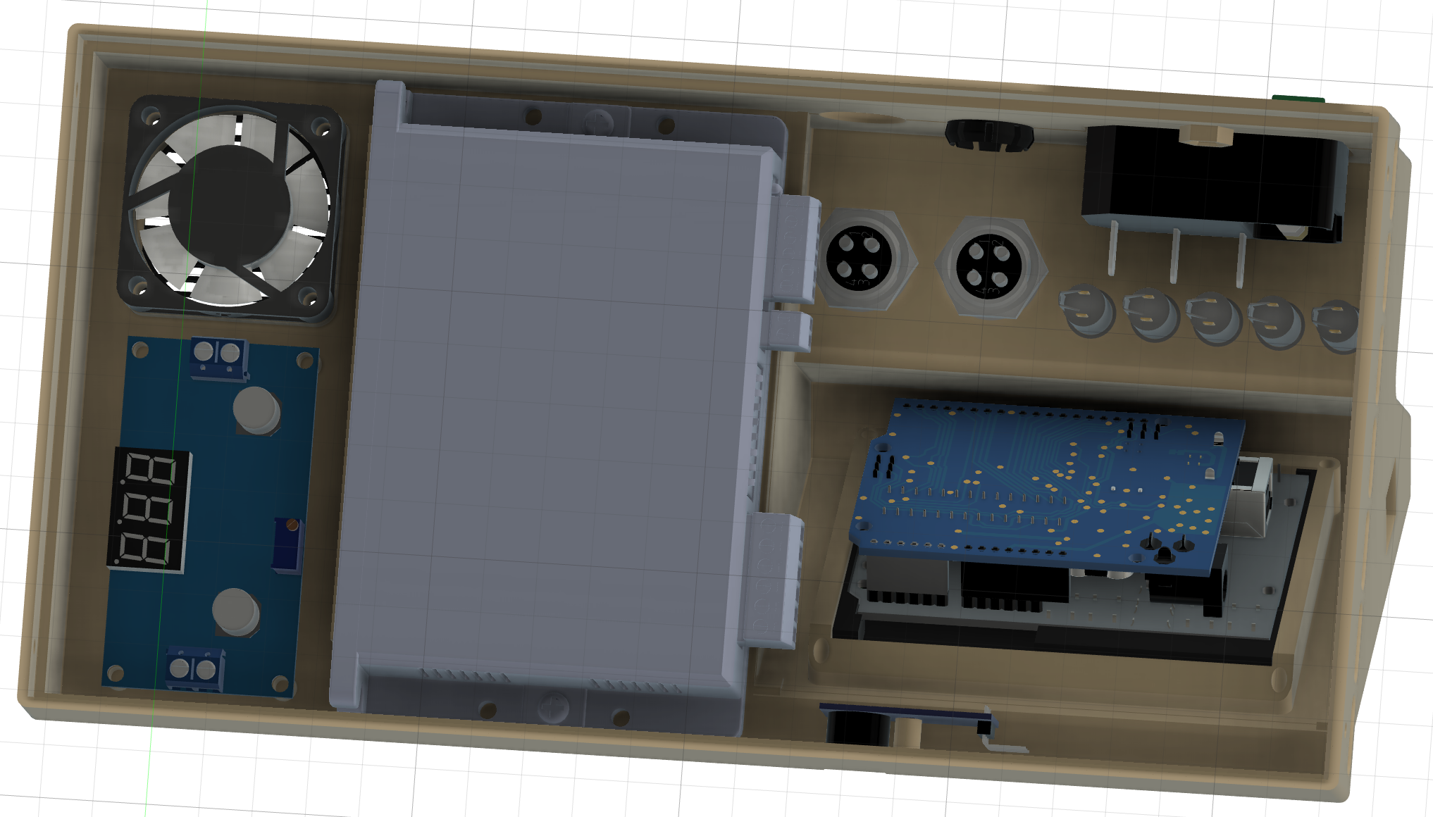
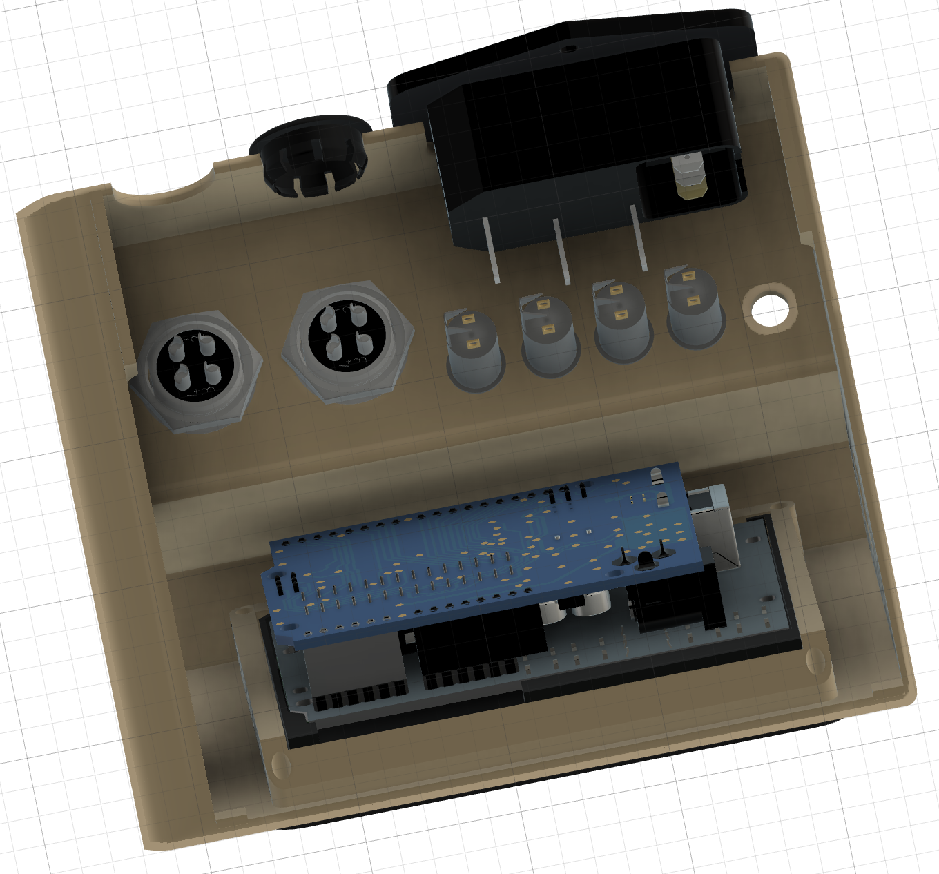
7) Control box
| Assembly views | |
|---|---|
 (click to zoom) |
 (click to zoom) |
 (click to zoom) |
 (click to zoom) |
- To attach the display mount to the main upper housing, simply slide the two small tabs in the front of the display mount in position and put in the screws to hold the mains connector in place, this will fix everything nice and tidy. It is a bit hard to describe, but take a look at the second image and you should see how this is going together.
- The stepper driver is held in place by friction. If your tolerances are a bit too loose you can use a bit of double sided tape to hold it in place.
- The fan has to blow the air out of the housing to achieve a good airflow.
- The power supply is just laying down inside the box. As I do not expect anyone to turn the control box upside down or shake it like crazy, there is simply no need for screws to hold it in place.
- I added two additional holes for GX16 connectors to the upper housing on purpose, which are not in use atm. Close them with two
control_box_GX16_blind_plug.stl. On the other hand, you could substitute the stereo jack connectors with GX16 connectors if you want, but you will have to adapt the wiring in this case.
As a sidenote, I know that there is not much room between the mains connector and the underside of the stereo jacks but this is no problem as long as you take care of isolating every single connector seriously. I used relatively thick shrink tubing around everything and it works without any problems.